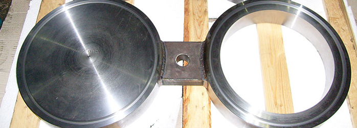
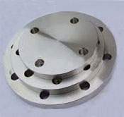
Welwin Pipes & Fittings is a dynamic group, which was established over a decade ago to cater to growing demands of Spectacle Blind Flanges standards in ASME / ANSI B16.5 Flanges,ASME/ANSI B16.47 etc in all materials like Stainless Steel , Carbon Steel & High Nickel Alloys. We Manufacture, Export and Supply Flanges which meets with national and international quality standards and producing base which owns equipments conforming to international technical level and is well equipped with a whole set of advanced plasma refining equipments.
We export our high quality Spectacle Blind flanges to Kuwait, Egypt and Qatar.
Range: ½” (15 NB) to 48” (1200NB)
Pressure Ratings: 150 LBS, 300 LBS, 600 LBS, 900 LBS, 1500 LBS, 2500 LBS ASA 150, ASA 300, PN 6,10,16,25, 40,64,100,160 ETC. available with NACE MR 01-75
Flange Facing Types
America Series:
Flat face(FF),Raised face(RF),Tongue(T),Groove(G),Female(F),Male(M),Ring type joints face(RJ/RTJ)
Europe Series:
Type A(Flat Face),Type B(Raised Face),Type C(Tongue),Type D(Groove),Type E(Spigot),Type F(Recess),Type G(O-Ring Spigot),Type H(O-Ring Groove)
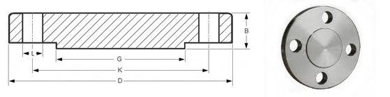
ANSI/ASME/ASA B16.5 150lb/sq.in. Flange BLIND-RF |
|||||||
ø |
D |
b |
g |
k |
Holes |
l |
Kg. |
1/2" |
88,9 |
11,1 |
34,9 |
60,3 |
4 |
15,9 |
0,400 |
3/4" |
98,4 |
12,7 |
42,9 |
69,8 |
4 |
15,9 |
0,700 |
1" |
107,9 |
14,3 |
50,8 |
79,4 |
4 |
15,9 |
0,900 |
1 1/4" |
117,5 |
15,9 |
63,5 |
88,9 |
4 |
15,9 |
1,300 |
1 1/2" |
127,0 |
17,5 |
73,0 |
98,4 |
4 |
15,9 |
1,600 |
2" |
152,4 |
19,0 |
92,1 |
120,6 |
4 |
19,0 |
2,600 |
2 1/2" |
177,8 |
22,2 |
104,8 |
139,4 |
4 |
19,0 |
4,100 |
3" |
190,5 |
23,8 |
127,0 |
152,4 |
4 |
19,0 |
5,000 |
3 1/2" |
215,9 |
23,8 |
139,7 |
177,8 |
8 |
19,0 |
6,400 |
4" |
228,6 |
23,8 |
157,2 |
190,5 |
8 |
19,0 |
7,100 |
5" |
254,0 |
23,8 |
185,7 |
215,9 |
8 |
22,2 |
9,000 |
6" |
279,4 |
25,4 |
215,9 |
241,3 |
8 |
22,2 |
11,800 |
8" |
342,9 |
28,6 |
269,9 |
298,4 |
8 |
22,2 |
21,000 |
10" |
406,4 |
30,2 |
323,4 |
361,9 |
12 |
25,4 |
30,000 |
12" |
482,6 |
31,7 |
381,0 |
431,8 |
12 |
25,4 |
45,000 |
14" |
533,4 |
34,9 |
412,7 |
476,2 |
12 |
28,6 |
59,000 |
16" |
596,9 |
36,5 |
469,9 |
539,9 |
16 |
28,6 |
79,000 |
18" |
635,0 |
39,7 |
533,4 |
577,8 |
16 |
31,7 |
97,000 |
20" |
698,5 |
42,9 |
584,2 |
635,0 |
20 |
31,7 |
124,000 |
22" |
749,3 |
46,0 |
641,2 |
692,1 |
20 |
34,9 |
151,000 |
24" |
812,8 |
47,6 |
692,1 |
749,3 |
20 |
34,9 |
188,000 |
ANSI/ASME/ASA B16.5 300lb/sq.in. Flange BLIND-RF |
|||||||
ø |
D |
b |
g |
k |
Holes |
l |
Kg. |
1/2" |
95,2 |
14,3 |
34,9 |
66,7 |
4 |
15,9 |
0,700 |
3/4" |
117,5 |
15,9 |
42,9 |
82,5 |
4 |
19,0 |
1,200 |
1" |
123,8 |
17,5 |
50,8 |
88,9 |
4 |
19,0 |
1,500 |
1 1/4" |
133,3 |
19,0 |
63,5 |
98,4 |
4 |
19,0 |
2,000 |
1 1/2" |
155,6 |
20,6 |
73,0 |
114,3 |
4 |
22,2 |
2,900 |
2" |
165,1 |
22,2 |
92,1 |
127,0 |
8 |
19,0 |
3,400 |
2 1/2" |
190,5 |
25,4 |
104,8 |
149,2 |
8 |
22,2 |
5,100 |
3" |
209,5 |
28,6 |
127,0 |
168,3 |
8 |
22,2 |
7,000 |
3 1/2" |
228,6 |
30,2 |
139,7 |
184,1 |
8 |
22,2 |
8,900 |
4" |
254,0 |
31,7 |
157,2 |
200,0 |
8 |
22,2 |
11,800 |
5" |
279,4 |
34,9 |
185,7 |
234,9 |
8 |
22,2 |
15,500 |
6" |
317,5 |
36,5 |
215,9 |
269,9 |
12 |
22,2 |
21,300 |
8" |
381,0 |
41,3 |
269,9 |
330,2 |
12 |
25,4 |
35,200 |
10" |
444,5 |
47,6 |
323,8 |
387,3 |
16 |
28,6 |
57,000 |
12" |
520,7 |
50,8 |
381,0 |
450,8 |
16 |
31,7 |
82,000 |
14" |
584,2 |
54,0 |
412,7 |
514,3 |
20 |
31,7 |
106,000 |
16" |
647,7 |
57,1 |
469,9 |
571,5 |
20 |
34,9 |
140,000 |
18" |
711,2 |
60,3 |
533,4 |
628,6 |
24 |
34,9 |
178,000 |
20" |
774,7 |
63,5 |
584,2 |
685,8 |
24 |
34,9 |
223,000 |
22" |
838,2 |
66,7 |
641,2 |
742,9 |
24 |
41,3 |
270,000 |
24" |
914,4 |
69,8 |
692,1 |
812,8 |
24 |
41,3 |
345,000 |
ANSI/ASME/ASA B16.5 600lb/sq.in. Flange BLIND-RF |
|||||||
ø |
D |
b |
g |
k |
Holes |
l |
Kg. |
1/2" |
95,2 |
14,3 |
34,9 |
66,7 |
4 |
15,9 |
0,700 |
3/4" |
117,5 |
15,9 |
42,9 |
82,5 |
4 |
19,0 |
1,200 |
1" |
123,8 |
17,5 |
50,8 |
88,9 |
4 |
19,0 |
1,500 |
1 1/4" |
133,3 |
20,6 |
63,5 |
98,4 |
4 |
19,0 |
2,000 |
1 1/2" |
155,6 |
22,2 |
73,0 |
114,3 |
4 |
22,2 |
3,200 |
2" |
165,1 |
25,4 |
92,1 |
127,0 |
8 |
19,0 |
4,300 |
2 1/2" |
190,5 |
28,6 |
104,8 |
149,2 |
8 |
22,2 |
6,000 |
3" |
209,5 |
31,7 |
127,0 |
168,3 |
8 |
22,2 |
8,000 |
3 1/2" |
228,6 |
34,9 |
139,7 |
184,1 |
8 |
25,4 |
10,500 |
4" |
273,0 |
38,1 |
157,2 |
215,9 |
8 |
25,4 |
18,000 |
5" |
330,2 |
44,4 |
185,7 |
266,7 |
8 |
28,6 |
28,500 |
6" |
355,6 |
47,6 |
215,9 |
292,1 |
12 |
28,6 |
35,500 |
8" |
419,1 |
55,6 |
269,9 |
349,2 |
12 |
31,7 |
58,000 |
10" |
508,0 |
63,5 |
323,8 |
431,8 |
16 |
34,9 |
98,000 |
12" |
558,8 |
66,7 |
381,0 |
488,9 |
20 |
34,9 |
125,000 |
14" |
603,2 |
69,8 |
412,7 |
527,0 |
20 |
38,1 |
151,000 |
16" |
685,8 |
76,2 |
469,9 |
603,2 |
20 |
41,3 |
215,000 |
18" |
742,9 |
82,5 |
533,4 |
654,0 |
20 |
44,4 |
287,000 |
20" |
812,8 |
88,9 |
584,2 |
723,9 |
24 |
44,4 |
366,000 |
22" |
869,9 |
95,2 |
641,2 |
777,9 |
24 |
47,6 |
437,000 |
24" |
939,8 |
101,6 |
692,1 |
838,2 |
24 |
50,8 |
532,000 |
Dimensional Tolerance of ASME B16.5 Weld Neck Flanges
| Outside Diameter ≤ 24 = 1.6 mm | > 24 = ± 3.2 mm |
Inside Diameter not applicable |
| Diameter of Contact Face 1.6 mm Raised Face = ± 0.8 mm 6.35 mm Raised Face, Tongue & Groove / Male-Female = ± 0.4 mm |
Outside Diameter of Hub ≤ 12 = + 2.4 mm / - 1.6 mm | ≥ 14 = ± 3.2 mm |
| Diameter of Counterbore not applicable |
Drilling Bolt Circle = 1.6 mm | Bolt Hole Spacing = ± 0.8 mm Eccentricity of Bolt Circle with Respect to Facing ≤ 2½ = 0.8 mm max. | ≥ 3 = 1.6 mm max. |
| Thickness ≤ 18 = + 3.2 mm / - 0 | ≥ 20 = + 4.8 mm / - 0 |
Length thru Hub ≤ 18 = + 3.2 mm / - 0.8 mm | ≥ 20 = + 4.8 mm / - 1.6 mm |
Notes
1. Dimensions are in millimeters unless otherwise indicated.
2. The length of the stud bolt does not include the height of the chamfers (points).
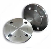
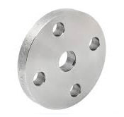
Stainless Steel Blind Flanges
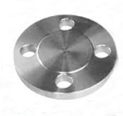
Carbon steel Blind Flanges
Duplex Steel Blind Flanges
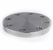
Nickel Alloy Blind Flanges
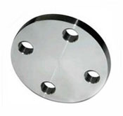
Inconel Blind flanges
Incoloy Blind Flanges
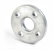
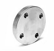
Hastelloy Blind Flanges
Monel Blind Flanges